Welcome to this new interesting and exciting tutorial dear networkseclearners. As shortly described in the previous article on ports and protocols, OSI model is a standard or model that defines how computers communicate and exchange data.
In the previous article on ports and protocols, we learnt that in the world of computer networking, communication between devices doesn’t happen randomly but follows a well structured process. One of the most important models used to understand this process is the OSI Model which stands for Open Systems Interconnection. If it is still abstract, don’t worry, we gonna deep dive into OSI.😊
Developed by the International Organization for Standardization (ISO), the OSI model breaks down network communication into seven layers, each with a specific role. From physically sending signals through cables to displaying data on a user screen and every step in the journey is handled by one of these layers.
Understanding the OSI model is essential for anyone working with networks because it helps identify where communication problems occur, design better systems and understand how different devices and technologies interact. More importantly, if you are planning on taking the CompTIA Network+ exam, this tutorial will be very useful to you because it covers the domain 1.0 Networking Concepts and Objective 1.1 which is : Explain concepts related to the Open Systems Interconnection(OSI) reference model.😉
As always, I will try my best to explain all the concepts in simple words that makes the understanding easier. So, stay focused and let’s get started with a short introduction on OSI model before deep diving into the seven layers. 😊
1. Introduction of the OSI model
The Open Systems Interconnection (OSI) Model was developed in 1977 by the International Organization for Standardization (ISO). It serves as a reference model that defines how data should flow across a network breaking the communication process into seven distinct layers. Each layer has a specific function and role in the journey of data from one device to another. We will deep dive into each layer in the following sections. 😉
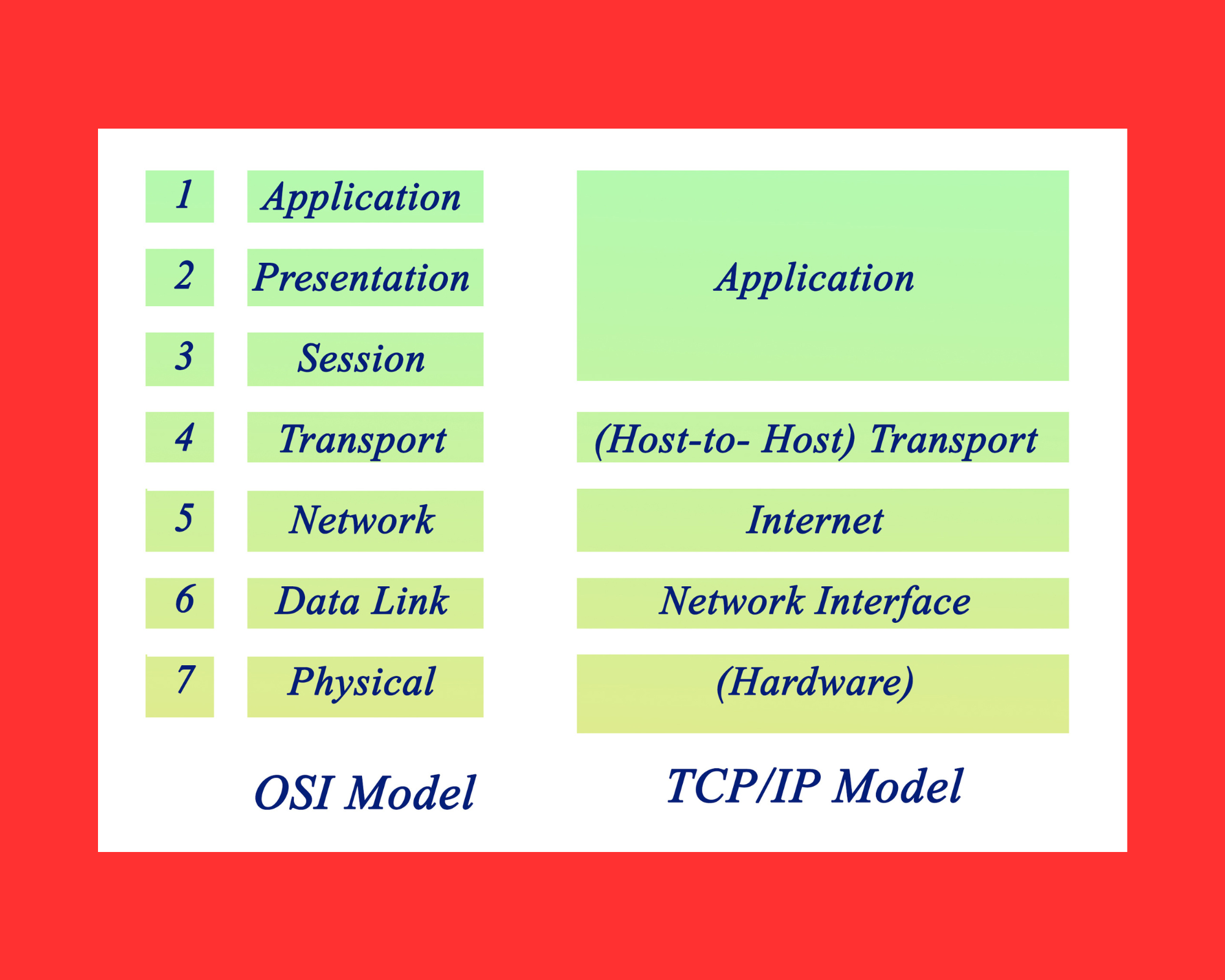
Although modern networks primarily operate using the TCP/IP model, the OSI model is still widely taught and used because it helps organize network functions in a way that is easy to understand and troubleshoot.
From sending raw electrical signals at the Physical Layer (Layer 1) to displaying information on your screen at the Application Layer (Layer 7), the OSI model gives a structured overview of how networks work. It even defines the specific name given to data as it moves through each layer from bits to frames, packets, segments, and finally just data at the higher layers. Now, let’s discuss into more details the layers.
2. Layers of the OSI model
2.1 Layer 1 : Physical
The Physical Layer is the very first layer of the OSI model. It deals with the actual physical way data is sent across a network. At this layer, the data is in its most basic form of bits basically 1s and 0s. This layer is responsible for how those bits are turned into signals and how they physically travel from one device to another. Thes bits are sent by switching between different physical signals :
- Over copper cables (like Cat5 or Cat6), the bit 1 might be represented by +5 volts, and 0 by 0 volts.
- In fiber optic cables, 1 can be represented by a flash of light (on) and 0 by no light (off).
This method of switching to represent 1s and 0s is called modulation. The most common connector you will see is the RJ-45 used in Ethernet cables. These cables are wired following certain standards :
- TIA/EIA-568A and TIA/EIA-568B are two standard wiring methods.
- A straight-through cable has the same standard on both ends (usually 568B).
- A crossover cable uses 568A on one end and 568B on the other, often used to connect similar devices directly.
This layer also defines the physical shape or layout of a network called its topology that we already covered in the tutorial on Computer Networks introduction. As a reminder, the common types include :
- Bus : All devices share one main cable.
- Ring : Devices form a closed loop.
- Star : Devices connect to a central point (like a switch).
- Hub and spoke : Like a star but often used in larger networks.
- Full mesh : Every device connects to every other device.
- Partial mesh : Some devices are fully connected, others are not.
Communication at this layer can happen :
- Asynchronously where each message starts and stops with special bits so devices know when the message begins and ends.
- Synchronously where both sides use a shared clock to stay in sync for real-time communication.
There are two main ways to use the cables capacity :
- Baseband : All the bandwidth is used for one signal at a time (like a regular phone call).
- Broadband : The bandwidth is split into separate channels like with cable TV.
Multiplexing is used to share a single connection more efficiently :
- TDM (Time Division Multiplexing) gives each user a fixed time slot.
- StatTDM (Statistical TDM) adjusts time slots based on who needs them.
- FDM (Frequency Division Multiplexing) splits the cable into different frequencies so multiple signals can go through at the same time.
Devices at this layer are purely physical and they just move the data without interpreting it :
- Cables like Ethernet, fiber optic, and coaxial
- Wireless signals like Wi-Fi, Bluetooth and NFC
- Basic hardware like hubs, access points, and media converters
These devices don’t make decisions or understand the data. They simply repeat or boost the signals to keep them moving along the network.
2.2 Layer 2 : Data Link
The Data Link Layer is the second layer of the OSI model. It takes the raw bits from Layer 1 (the Physical Layer) and organizes them into frames so that data can travel across a network smoothly and reliably.
This layer is responsible for several important jobs :
- It packages bits into frames.
- It checks for errors and corrects them when possible.
- It identifies devices on the network using something called a MAC address.
- It manages how much data is sent at a time to avoid overwhelming devices (this is called flow control).
2.2.1 MAC Address (Media Access Control)
Every device connected to a network has something called a MAC address which is a unique identifier assigned to its network interface card (NIC). You can think of a MAC address like a permanent name tag for a device on a network. MAC is 48 bits long and written in hexadecimal (example 00:1A:2B:3C:4D:5E). The first half of the MAC address identifies the manufacturer whereas the second half is unique to each device.
MAC addresses are crucial for identifying who is who on the network especially in local networks where IP addresses might change but MAC addresses don’t.
2.2.2 LLC (Logical Link Control)
The Data Link Layer has two sublayers. One of them is called LLC (Logical Link Control) and its job is to help control how devices talk to each other :
- Acknowledge that a message was received.
- Control how much data gets sent so the receiver doesn’t get overloaded.
- Check whether data was corrupted during transmission using a checksum.
2.2.3 Synchronization of devices at layer 2
Layer 2 also handles how devices stay synchronized when they communicate and it uses three main methods in order to achieve this :
- Isochronous : Devices use a shared clock and take turns sending data in time slots. It is very organized and has less overhead.
- Synchronous : Devices use the same clock and mark the start and end of each message with special characters.
- Asynchronous : Devices use their own internal clocks and rely on start and stop bits to manage timing. This is more flexible but less precise.
2.2.4 Devices at Layer 2
Several important network devices operate at this layer including :
- Network Interface Cards (NICs) : the physical cards inside your device that connect you to the network.
- Bridges : devices that connect two different parts of a network and help control traffic between them.
- Switches : smart devices that can learn which MAC address is connected to which port. They use something called a CAM table to make decisions about where to send data. Switches are especially important because they make sure that network data gets delivered only to the intended device instead of flooding the entire network.
2.3 Network Layer
The Network Layer is responsible for moving data between different networks. This is where routing happens finding the best path for data to travel from one device to another using logical addresses like IP addresses.
2.3.1 Logical Addressing
At this layer, devices are identified using logical addresses instead of physical ones like MAC addresses.
The most common logical addresses are :
- IPv4 : This is written as four numbers separated by dots like 192.168.1.1 Each number can range from 0 to 255.
- IPv6 : A newer format designed to handle more devices using longer addresses like 2001:0db8:85a3::8a2e:0370:7334.
Before IP became the standard, other protocols like AppleTalk and IPX were used but they are now mostly obsolete.
2.3.2 Switching and Routing Methods
There are several ways to move data across a network :
- Packet Switching (Routing) : This is the most common method. Data is split into smaller pieces called packets. Each packet may take a different path to the destination and they are reassembled at the end.
- Circuit Switching : A dedicated path is established between two devices before any data is sent. It is like making a phone call where nobody else can use that line during the call.
- Message Switching : Whole messages are sent and stored temporarily on devices along the way before being forwarded to the destination. This isn’t used much today due to delays.
Routers figure out the best path for data using something called a routing table. Dynamic routing protocols like RIP (Routing Information Protocol) and OSPF (Open Shortest Path First) help routers automatically update their tables and share path info with each other. These protocols make sure data takes the fastest and most efficient route possible.
2.3.3 Connection Services at Layer 3
While most flow control happens at Layer 2, Layer 3 also helps with :
- Flow control : Preventing one device from sending too much data too fast.
- Packet reordering : Making sure packets are reassembled in the right order after taking different paths across the network.
2.3.4 Devices and Protocols at Layer 3
The main devices that work at this layer are :
- Routers : These are the traffic managers of the internet. They decide where packets should go based on their destination IP address.
- Multilayer switches : These combine the functions of both a regular switch (Layer 2) and a router (Layer 3). They can make routing decisions but still behave like a switch.
Common protocols used at this layer :
- IPv4
- IPv6
- ICMP
2.4 Transport layer
The Transport Layer is the bridge between the lower layers (which deal with hardware and transmission) and the upper layers (which handle what the user actually interacts with like apps and data formatting). This layer is mainly responsible for delivering data reliably (or quickly, depending on the protocol) from one device to another. At this layer, the data is broken down into segments (if using TCP) or datagrams (if using UDP). Key Protocols at Layer 4 are therefore TCP and UDP.
2.4.1 Devices that operate at this layer:
- WAN accelerators : optimize data transfers across wide area networks
- Load balancers : distribute traffic evenly across servers
- Firewalls : control traffic based on transport-layer details (like port numbers)
2.5 Session Layer
The Session Layer is like a conversation manager. It makes sure two devices can talk to each other without mixing up their messages. It starts, maintains and ends these communication sessions. Think of it like a customer support call :
- You get connected (session setup)
- You stay on the line and talk (session maintenance)
- You say goodbye and hang up (session teardown)
2.5.1 Session Principles
- Setting Up a Session
- Starts a connection between two devices.
- It might verify credentials (like username/password).
- It assigns unique session IDs so that multiple conversations can happen at the same time without confusion.
- Maintaining the Session
- Keeps the session active while data is being exchanged.
- If the connection breaks (like a dropped call), the session may need to be restarted.
- Tracks who sent what and confirms that data is received.
- Tearing Down a Session
- Once the conversation is over, the session is gracefully closed.
- Either side can end the session.
2.5.2 Protocols and Examples
The Session Layer doesn’t usually involve hardware devices, but it does use specific protocols and software :
- H.323 : Used for voice and video calls like in VoIP or video conferencing.
- It works alongside RTP (Real-time Transport Protocol) to deliver real-time communication smoothly.
- Helps set up, manage, and end the calls.
- NetBIOS : Used mainly for Windows file sharing over a network.
- Helps computers find and talk to each other on local networks.
2.6 Presentation
The Presentation Layer is like a translator and security guard for your data.
Its job is to format and encrypt data so that different systems can understand each other and data stays secure during transmission.
2.6.1 Data Formatting
Makes sure data from the sender looks correct and understandable to the receiver. Think of it like subtitling a movie in the right language so viewers can understand. This is useful because for example a Windows PC and a Mac might “speak” different digital dialects. The Presentation Layer ensures they both understand the data the same way.
Examples of formatting :
- ASCII Used for basic text
- JPEG, PNG, GIF formats for images and motion.
- MP4, MOV which are formats for videos.
2.6.2 Encryption
Scrambles data to keep it private and secure while it travels across the network.Think of it like locking your data in a safe before shipping it. Encryption protocols as these ones are used :
- TLS (Transport Layer Security) creates a secure tunnel between sender and receiver.
- SSL (Secure Sockets Layer) which is an older version of TLS.
In order to understand easily, imagine sending a birthday card to someone in another country:
- You translate the message into their language (formatting).
- You put it in a locked envelope so nobody can read it on the way (encryption).
- The Presentation Layer does both before handing the message to the application.
2.7 Application
The Application Layer is the seventh and topmost layer of the OSI model. It provides network services directly to end-user applications and enables communication between software applications and lower OSI layers :
- Facilitates interaction between the user and the network
- Provides services for file transfers, email, web access and remote connections
- Works with lower layers to deliver data, but does not include the applications themselves (like web browsers)
2.7.1 Key Functions
Application Services
Supports multiple applications that use the same network connection. Common services include File transfer, File sharing, Email, Remote access and Network management.
Service Advertisement
Devices on a network announce their services so other devices can find and use them Examples include File servers, printers (using Active Directory) and Self-advertising devices like wireless printers.
2.7.2 Common Layer 7 Protocols
2.7.2.1 Email Protocols
- POP3 (Post Office Protocol 3): Downloads emails from a server and removes them
- IMAP (Internet Message Access Protocol): Accesses and syncs email across devices
- SMTP (Simple Mail Transfer Protocol): Sends emails from clients to servers
2.7.2.2 Web Browsing Protocols
- HTTP (Hypertext Transfer Protocol) : Used for loading web pages (unencrypted)
- HTTPS (HTTP Secure) : Secure web browsing using TLS encryption
2.7.2.3 File Transfer Protocols
- FTP (File Transfer Protocol) : Transfers files over a network
- FTPS (FTP Secure) : FTP with SSL encryption
- SFTP (SSH File Transfer Protocol) : Secure file transfer over SSH
2.7.2.4 Remote Access Protocols
- Telnet: Basic remote control over a device (not secure)
- SSH (Secure Shell): Secure remote access to systems
- SNMP (Simple Network Management Protocol): Used for managing network devices
3. Encapsulation and Decapsulation
- Encapsulation : Adding headers (and sometimes trailers) to data as it moves down from Layer 7 to Layer 1.
- Decapsulation : Removing those headers/trailers as data moves up from Layer 1 to Layer 7.
4. Protocol Data Units (PDUs) in OSI
Each layer has its own term for a unit of data :
- Layer 1 (Physical) : Bits
- Layer 2 (Data Link) : Frames
- Layer 3 (Network) : Packets
- Layer 4 (Transport) : Segments (TCP) or Datagrams (UDP)
- Layer 5–7 : Referred to generically as L5 PDU, L6 PDU, and L7 PDU
The Application Layer acts as a bridge between user-facing applications and the OSI model providing access to essential network services. Although it doesn’t contain the actual applications, it enables them to function by offering the underlying network protocols and processes they rely on.
CONCLUSION
And there you have it the magical Layer 7, the Application Layer where all the action actually feels real to us humans. Whether you are sending an email, streaming cat videos or asking your smart fridge to order more ice cream, it is Layer 7 working behind the scenes to make the internet feel like magic.😊
If this article helped you finally make sense of this networking wizardry, do us (and your fellow learners) a favor by sharing it! Pass it on to a friend who still thinks “IP” stands for “Important Person,” or that DNS is just “Do Not Share.”
Stay curious, keep learning, and may your packets always arrive in order!😊
WOW just what I was searching for.